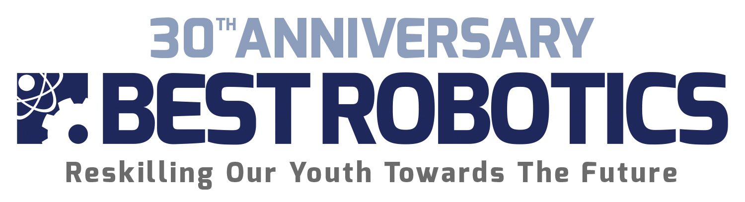
As the number of teams grew larger at hubs and the Texas BEST championship, there were simply not enough Radio Frequencies available to ensure that no teams would interfere with one another. To solve this dilemma, Steve and Ted invented the Tether System by taking advantage of an interesting feature of the RC controller called “Trainer Mode”. The robot could be connected in 3 different ways:
- Normal RC use at the school, away from other transmitters and possible interference.
- Robot directly tethered to the transmitter; used on game day in the PIT area to avoid using radio frequencies.
- Field transmitter and receiver; used on game day to avoid overlapping radio frequencies.
The complete Tether System consisted of the team transmitter, team receiver, robot box, and tether box distributed to each team AND a field transmitter and field receiver used exclusively on the game field.
Hubs would limit the number of frequencies being used during a competition to only 4 (i.e., the 4 teams on the field) and use configuration 3. Field transmitters with the 4 dedicated frequencies were built into PVC pipe towers at the field, near each driver area. Teams were handed a special Field Receiver Box to connect to their robot when they competed that matched the frequency of the transmitter on the field where they would participate. This Receiver Box needed to a way to quickly disconnect from the robot rather than disconnecting all of the motor and servo PWM wires each time. So, the Robot Box was created to connect the Receiver Box to the robot through a simple ribbon cable; all robot wires could remain connected to the Robot Box which was never removed from the Robot. When a team was ready to play in their match, they connected the Receiver Box handed to them during staging, then plug their RC transmitter into the tower (Field Transmitter) at their field quadrant. This essentially put their transmitter in “Training Mode” and allowed it to control the operations of the Field Transmitter (the one with the actual frequency matching the Receiver Box on their robot) with their own Team’s transmitter.
More on the Field Transmitters here.
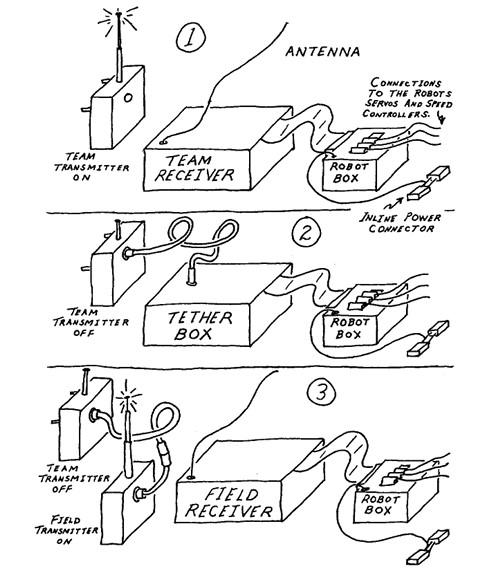
Is your head hurting yet? So, this solved the problem of conflicting frequencies ON THE FIELD. What about teams practicing in the PIT area? For this final piece to the puzzle….Steve and Ted decided to solve this problem by again using the trainer port on the back of the Team transmitter to directly connect to the Robot Box and allow the robot to be operated via a ‘Tether’ (i.e., a cable directly connecting the tranmitter to the robot, no RF frequencies used — configuration 2 in the diagram). For this all to work, the crystal oscillator in each of the Team transmitters had to be removed on Game Day. This ensured that no team transmitter could produce any RF frequency and cause interference. The crystals are made to be removable on these RC transmitters so that frequencies can be changed when desired. Wow….thank goodness for that! The crystals were taken from each team during Robot Compliance and returned at the conclusion of Game Day.
Now the fun part….hub volunteers had to “assembly” these 3 custom “boxes” that were included the Return Kit: Robot Box, Receiver Box, Tether Box. BEST Robotics had the pc boards manufactured, bulk ordered and precut all of the enclosures, cables, and fasteners; hubs ordered the Tether System components through the BRI Ordering System annually. Steve Marum spent many a night kitting tether system components and visiting the UPS store.
Once the hub received the components, some final assembly was still needed. Here are the actual instructions distributed for assembling the Tether System. And you thought kitting the consumable parts was the only manual labor required…
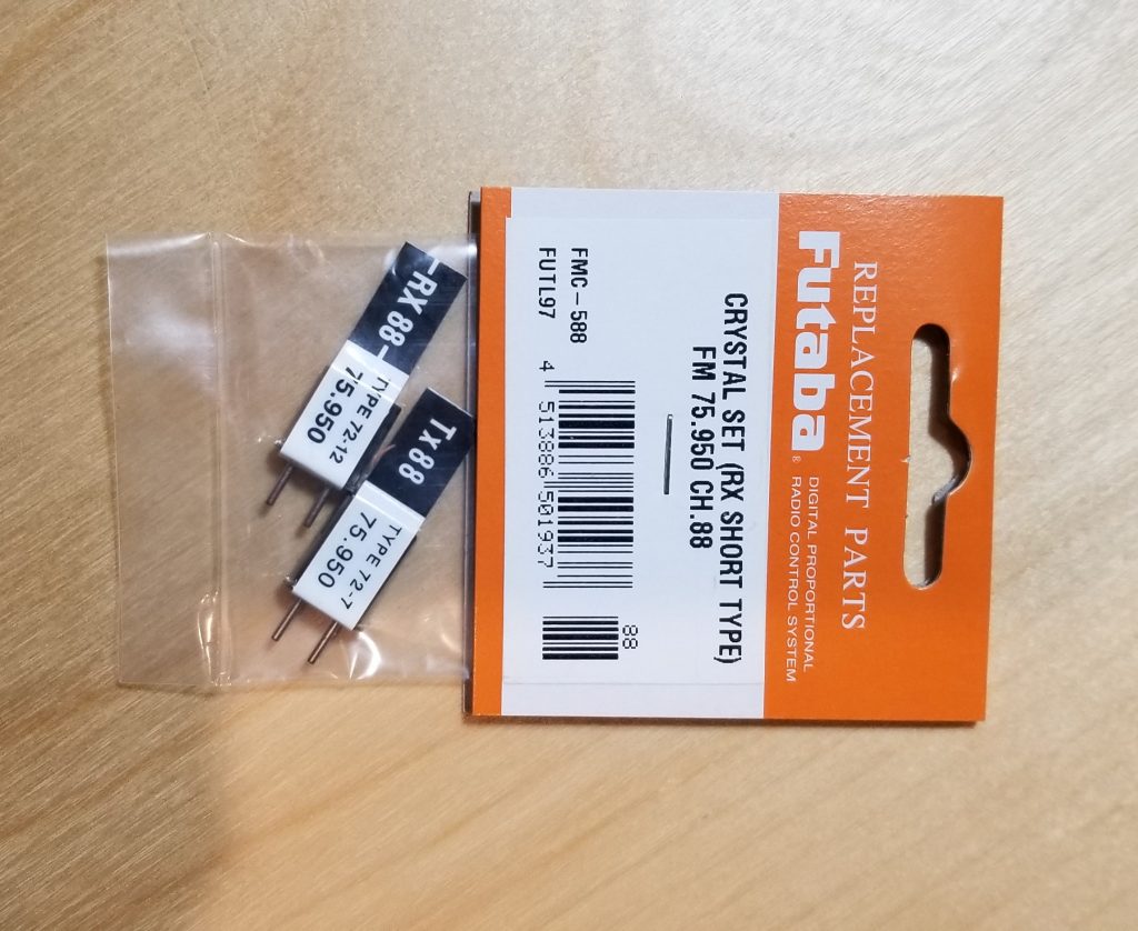
Return Kit with Tether System
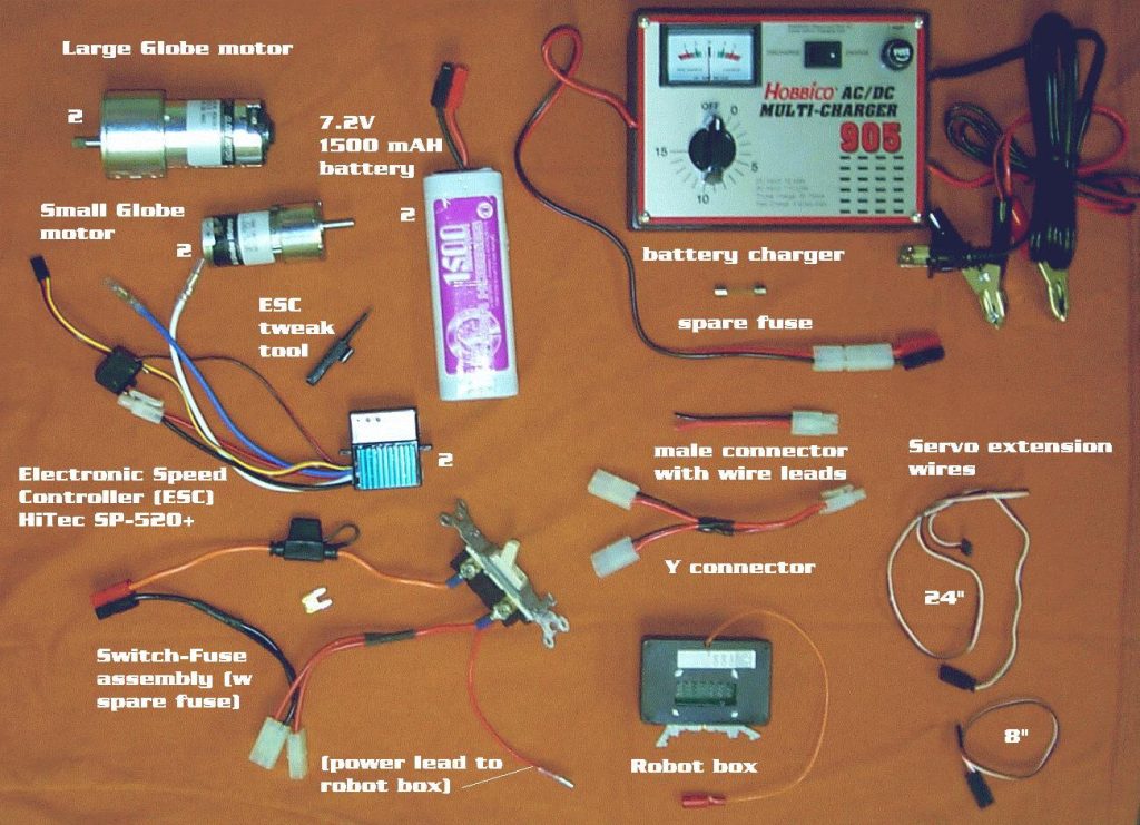
Here is the Return Kit BEFORE programming was introduced. You can see the Futaba Transmitter, Receiver (inside the Receiver Box), and the full tether system (Robot Box, Tether Box, Tether cable). You’ll also see early wiring components (Switch-Fuse assembly, Y connector) and motor speed controllers.
Early Kit Notes
Here is an early Kit Notes document that described the Return Kit with tether system and its operation.